
To test a thermostat under thermal cycling conditions, you expose it to repeated, controlled swings between a low temperature and a high temperature, then measure whether its opening point, stroke, and sealing behavior remain within specification after each sequence of cycles. The goal is to simulate years of real-world heating and cooling in a compressed timeframe, revealing whether the wax element, housing, and sealing surfaces can hold up under sustained mechanical and thermal stress. The sections below walk through the key questions engineers and procurement teams ask when designing or evaluating a thermal cycling test program.
What temperature range is used in thermostat thermal cycling tests?
A standard thermostat thermal cycling test typically spans from a low extreme of around -40°C up to a high extreme that exceeds the thermostat’s rated opening temperature by at least 20°C to 30°C. For an automotive engine thermostat rated to open at 87°C, the upper end of the cycle often reaches 110°C to 130°C, while industrial thermostats may be tested at even higher peaks depending on their application.
The cold soak temperature matters just as much as the heat. Dropping to -40°C forces the wax element to contract fully and the sealing surfaces to close under conditions that mimic cold starts in extreme climates. The transition between these extremes is also controlled: ramp rates are defined so that the component is not shocked faster than it would experience in service, but fast enough to produce meaningful mechanical fatigue within a reasonable number of test hours. Some test protocols specify a dwell time at each extreme, holding the thermostat at peak cold or peak heat for a fixed period before the next ramp begins.
What equipment is needed to run a thermal cycling test?
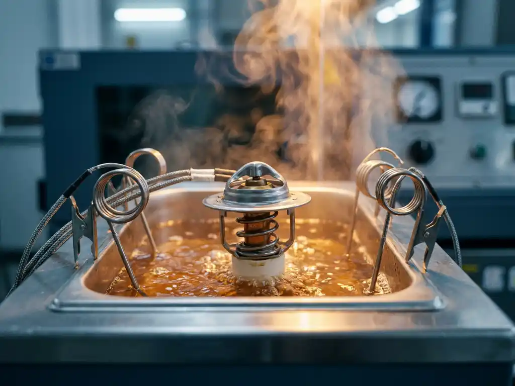
Running a proper thermostat thermal cycling test requires a temperature-controlled fluid bath or a climate chamber capable of hitting the full test range, a calibrated displacement sensor to track valve stroke, a data acquisition system that logs temperature and position continuously, and a pressure source if the test protocol requires the thermostat to seal against a defined backpressure during cycling.
Fluid baths are the most common setup for automotive thermostats because the component is designed to operate in liquid coolant. The bath fluid must be compatible with the thermostat’s materials across the full temperature range, which usually means a water-glycol mixture similar to actual engine coolant. For dry-environment or industrial thermostats, air-circulating climate chambers are used instead.
Calibration is non-negotiable. Temperature sensors placed at the thermostat’s sensing point must be accurate to within ±0.5°C or better, because even small offsets will distort the opening and closing temperature readings that form the core of the performance record. Displacement sensors should have resolution in the range of 0.01 mm to capture early signs of stroke reduction before it becomes a functional failure.
How many cycles does a thermostat need to pass?
The required number of thermal cycles depends on the application, but automotive thermostats are typically expected to pass between 6,000 and 15,000 full thermal cycles without exceeding defined drift limits. Industrial and HVAC thermostats may have different cycle targets set by the relevant industry standard or by the customer’s own specification.
The cycle count is not arbitrary. It is derived from field data on how many heating and cooling events a component will experience across its expected service life. A passenger car thermostat that must last ten years and 200,000 kilometers will go through thousands of warm-up and cool-down events, and the test program compresses those events into a laboratory sequence. Some OEM specifications add additional robustness margin by requiring the component to pass more cycles than the minimum field estimate.
Intermediate checks are built into most protocols. Rather than running all cycles and inspecting only at the end, engineers pull the thermostat at defined intervals, such as every 1,000 or 2,500 cycles, to measure opening temperature, full stroke, and leak tightness. This staged approach reveals whether degradation is gradual and linear or whether it accelerates suddenly after a threshold is crossed.
What failure modes does thermal cycling reveal in thermostats?
Thermal cycling testing reveals several distinct failure modes that would not appear in a single-point functional test. The most common are opening temperature drift, stroke reduction, and internal or external leakage. Each of these has a different root cause and points to a different aspect of component design or manufacturing quality.
Opening temperature drift
Over repeated cycles, the wax element can lose its precise calibration if the wax compound degrades, if contaminants enter the element, or if the element housing develops micro-deformation. The result is a thermostat that opens earlier or later than its rated temperature, which in an engine means the coolant circuit runs either too cold or too hot. Even a drift of 3°C to 5°C can push an engine outside its optimal thermal window and affect fuel consumption and emissions.
Stroke reduction and seal degradation
Mechanical fatigue in the wax element’s piston and guide surfaces can reduce the total valve stroke over time. A thermostat that originally opened to a full stroke of 8 mm may open to only 6 mm after extended cycling, restricting coolant flow and reducing the system’s ability to regulate temperature at high load. Separately, the sealing surfaces between the valve and its seat can wear or deform, leading to internal bypass leakage even when the thermostat is nominally closed. This leakage is particularly damaging in cold-start conditions where the engine needs to heat up quickly.
How do you measure thermostat performance after each cycle?
After each measurement interval in a thermal cycling test, performance is assessed by recording the opening start temperature, the temperature at full stroke, the total stroke distance, and the leak rate at a defined pressure. These four parameters together give a complete picture of whether the thermostat is still functioning within its design specification.
The measurement procedure typically involves placing the thermostat in a fresh, clean fluid bath at a controlled starting temperature, then ramping the temperature slowly at a defined rate, usually 1°C to 2°C per minute, while the displacement sensor tracks valve movement continuously. The temperature at which the valve first moves is recorded as the opening start point, and the temperature at which maximum stroke is reached is the full-open point. Both values are compared against the original specification and against previous interval readings to identify any trend.
Leak testing is performed with the thermostat held closed against a defined pressure differential. Any measurable flow through the closed valve above the permitted limit counts as a failure. Engineers also perform a visual inspection at each interval, looking for cracks in the housing, corrosion on metal surfaces, or visible deformation of the wax element body. These visual findings often precede measurable functional degradation and provide early warning before a component actually fails.
For teams sourcing thermostat components, understanding what these measurements look like in practice helps set realistic acceptance criteria when reviewing supplier test reports.
How does thermal cycling testing differ for automotive versus industrial thermostats?
Automotive and industrial thermostat thermal cycling tests share the same underlying logic but differ in temperature range, cycle count, fluid environment, and the specific failure criteria that matter most. Automotive tests prioritize tight opening-temperature tolerance and rapid response, while industrial tests often emphasize long-term stability under sustained high temperatures and compatibility with a wider range of process fluids.
Automotive thermostat testing
Automotive thermal cycling tests are governed by OEM-specific standards and general industry guidelines that reflect the demanding environment of a combustion engine or electric powertrain cooling circuit. The temperature swings are wide, the cycle counts are high, and the tolerance bands for opening temperature are tight, often ±2°C or less. The fluid environment is standardized coolant, and tests are frequently combined with vibration or pressure cycling to simulate the full engine bay environment. Response speed also matters: an automotive thermostat must begin opening within a defined time after the set point is reached, and slow response is treated as a failure.
Industrial thermostat testing
Industrial thermostats used in hydraulic systems, marine cooling circuits, or process equipment face different stresses. Cycle counts may be lower because industrial equipment runs fewer start-stop events per year than a passenger car, but the operating temperatures are often higher and the fluids more aggressive. Test protocols for industrial applications tend to place greater emphasis on long dwell times at elevated temperature, compatibility testing with specific process fluids, and resistance to corrosion or scaling. The acceptable drift in opening temperature may also be wider than in automotive applications, reflecting the less precise thermal management requirements of many industrial processes. That said, applications like precision cooling systems in manufacturing equipment can demand tolerances as tight as any automotive specification.
How BTT Solutions supports thermostat testing and component selection
We work closely with customers across the automotive, industrial, and building technology sectors to make sure the thermostat components they select are not just functionally correct on paper but proven under the real thermal cycling conditions their application demands. Our approach to component advisory covers the full picture:
- Application-specific component matching: We help customers identify the right wax element type, thermostat insert, and housing configuration based on their actual operating temperature range, fluid environment, and cycle load.
- Test documentation support: We provide detailed test data and thermal cycling results for our components, so your engineering team can validate performance against your own acceptance criteria without starting from scratch.
- Custom specification alignment: Where standard products need to be adapted to meet a specific OEM or industrial standard, our team works through the specification requirements and advises on the most efficient path to qualification.
- Responsive technical dialogue: As a focused, mid-sized company, we give customers direct access to the engineers who designed and tested the products, not just a sales contact who relays questions.
If you are evaluating thermostats for a new application or reviewing the durability requirements for an existing design, we are ready to help. Get in touch with our team to discuss your specific thermal cycling requirements and find the right component for your needs.
Related Articles
- How does consistent temperature control reduce engine wear?
- How does faster warm-up contribute to CO2 reduction in vehicles?
- What are the most common automotive thermostat component failures?
- What factors should OEMs consider when selecting a thermostat supplier?
- How do oil temperature regulators work in hydraulic systems?


