
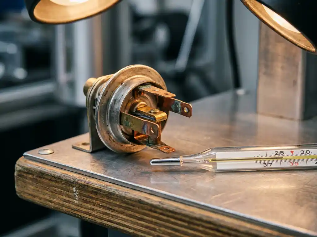
Electrical contact resistance directly reduces thermostat accuracy by introducing a voltage drop across sensor connections, which causes the control circuit to read a temperature that differs from the actual value. Even a small increase in resistance can shift a temperature reading by several degrees, enough to affect system performance in precision-sensitive applications. The sections below break down the causes, thresholds, and practical remedies worth knowing.
How does electrical contact resistance alter temperature readings?
Electrical contact resistance distorts temperature readings by adding an unwanted resistance value into the measurement circuit. Because most thermostat circuits infer temperature from a voltage or resistance signal, any additional resistance at a contact point is interpreted as a higher or lower temperature than actually exists, producing a systematic measurement error.
In a typical thermistor-based circuit, the sensor’s resistance changes predictably with temperature. When contact resistance is added at a connector, terminal, or solder joint, the total measured resistance rises above what the thermistor alone would show. The control unit then maps this inflated resistance value to a temperature reading that is offset from reality. Depending on the circuit topology, this can cause a system to heat or cool beyond the intended setpoint before the thermostat responds.
The effect is not always constant. Contact resistance can fluctuate with vibration, moisture ingress, and thermal cycling, which means the measurement error can shift over time. This variability is particularly problematic in applications where stable, repeatable temperature control is critical, such as engine coolant management or industrial fluid regulation.
What causes contact resistance to increase in thermostat components?
Contact resistance in thermostat components increases primarily due to oxidation, contamination, mechanical wear, and poor initial assembly. Each of these factors raises the impedance at the interface between two conductive surfaces, degrading the quality of the electrical signal passing through the connection.
- Oxidation: Metal surfaces exposed to air and moisture form oxide layers that are far less conductive than the base metal. Copper and aluminium contacts are especially susceptible, and the effect accelerates at higher operating temperatures.
- Contamination: Oils, coolant residue, and particulate matter can settle on contact surfaces, introducing insulating films that raise resistance unpredictably.
- Mechanical wear: Repeated mating and unmating of connectors, or vibration-induced micro-motion, gradually degrades the contact surface and reduces the effective contact area.
- Thermal cycling: Expansion and contraction of materials over many temperature cycles can loosen crimped or press-fit connections, reducing the clamping force that maintains good electrical contact.
- Poor assembly: Insufficient crimp force, cold solder joints, or undersized contact springs all create elevated resistance from the outset, before any degradation has occurred.
Understanding which of these mechanisms is dominant in a given application helps engineers choose the right contact material, plating, and connection method from the start rather than addressing problems after deployment.
How much contact resistance is too much for precise temperature control?
For most precision thermostat and temperature sensor circuits, contact resistance above a few ohms begins to introduce meaningful measurement error, and values above ten ohms can cause significant inaccuracy. The exact threshold depends on the sensor type and circuit design, but the general principle is that any contact resistance comparable in magnitude to the sensor’s own resistance range will distort the reading.
A common thermistor used in automotive or HVAC applications might have a nominal resistance of several kilohms at mid-range temperatures. In that context, a contact resistance of a few ohms represents a small fraction of the total, and its effect on accuracy is minor. However, at high temperatures where the thermistor resistance drops to the low hundreds of ohms, even a modest contact resistance of ten to twenty ohms can represent a measurable percentage of the total circuit resistance and shift the reading noticeably.
For precision thermostat components used in emissions-sensitive or safety-critical applications, design targets typically aim to keep contact resistance well below one ohm per connection. This headroom accounts for the resistance increase that occurs naturally over the product’s service life.
Does contact resistance affect all thermostat types equally?
No, contact resistance affects different thermostat types to varying degrees. Resistance-based sensors such as thermistors and RTDs are directly and proportionally affected because the measurement relies on reading an accurate resistance value. Voltage-output sensors and thermocouples are less sensitive to contact resistance but are not entirely immune, particularly when contact resistance is high enough to affect signal integrity.
Thermistors and RTDs
These sensors are the most vulnerable to thermistor contact resistance errors because the entire measurement depends on reading the sensor’s resistance accurately. Any series resistance added by a poor contact adds directly to the measured value, creating a predictable but potentially significant offset. In four-wire RTD configurations, the measurement circuit is specifically designed to exclude lead and contact resistance, making this topology far more robust for high-precision applications.
Bimetallic and wax-element thermostats
Mechanical thermostat types that use physical actuation rather than electronic sensing are affected differently. Here, contact resistance matters at the switching contacts rather than in a measurement circuit. High contact resistance at the switching point causes resistive heating at the contact itself, which can cause the thermostat to respond to its own self-generated heat rather than the surrounding fluid temperature, a phenomenon sometimes called thermal feedback error.
How can contact resistance in thermostat circuits be minimised?
Contact resistance in thermostat circuits can be minimised through careful material selection, appropriate surface finishing, robust connector design, and disciplined assembly practices. Addressing resistance at the design stage is far more effective than attempting to compensate for it in software or through calibration after the fact.
- Use gold or silver plating on contacts: These materials resist oxidation far better than bare copper or tin, maintaining low contact resistance over the product’s service life.
- Specify adequate contact force: Higher contact force breaks through thin oxide layers and increases the effective contact area. Connector specifications should include a minimum normal force appropriate for the environment.
- Seal connectors against moisture and contamination: Sealed connector housings and appropriate IP ratings prevent the ingress that accelerates oxidation and contamination.
- Apply contact lubricants where appropriate: Specialised connector lubricants can inhibit oxidation and reduce fretting wear caused by micro-vibration.
- Use four-wire measurement for high-precision sensors: In RTD circuits, four-wire (Kelvin) connections eliminate the effect of lead and contact resistance entirely from the measurement, which is the most reliable engineering solution for precision-critical applications.
- Validate crimp and solder quality during assembly: Process controls that verify crimp height and pull-out force, combined with solder joint inspection, catch high-resistance connections before they reach the field.
When should contact resistance be tested in thermostat assemblies?
Contact resistance should be tested at three key points: during incoming inspection of components, at the end of the assembly process, and as part of periodic maintenance or field validation. Testing at each of these stages catches different failure modes and prevents high-resistance connections from reaching or degrading in service.
During incoming inspection, testing connector contacts and sensor leads establishes a baseline and identifies components that fall outside specification before they are built into an assembly. End-of-line testing after assembly confirms that the assembly process itself has not introduced resistance through poor crimping, cold solder joints, or connector damage. This is the last opportunity to catch problems before a product reaches the customer.
In the field, periodic resistance testing is valuable for assemblies operating in harsh environments where oxidation and vibration are ongoing stressors. Comparing current contact resistance values against the original baseline makes it possible to identify connections that are degrading before they cause a measurable impact on thermostat performance. For critical applications in automotive or industrial systems, this kind of proactive monitoring can prevent unplanned downtime.
Testing is typically performed with a milliohmmeter or a four-wire resistance measurement instrument, which applies a small known current through the contact and measures the resulting voltage drop. This method accurately resolves resistance values in the milliohm range, well below the thresholds that matter for temperature sensor accuracy.
How BTT Solutions supports thermostat accuracy in your application
Getting contact resistance right from the start is a design and manufacturing challenge, not just a maintenance problem. At BTT Solutions, we work directly with engineering and procurement teams to ensure the thermostat components they specify are built to maintain low contact resistance throughout their service life. Our product advisory service covers the full range of thermostat components, including wax elements, thermostat inserts, and engineered housings, and we help customers match the right component to their specific thermal management requirements.
When you work with us, you benefit from:
- Expert guidance on component selection for automotive, industrial, and building technology applications
- Products designed and tested for precision and long-term reliability, including validated contact and connection integrity
- Direct access to our engineering team, with the responsiveness that comes from a focused, mid-sized organisation
- End-to-end support from specification through to application, without being passed between departments
If you are evaluating thermostat components for a new application or troubleshooting accuracy issues in an existing system, we are ready to help. Get in touch with our team to discuss your requirements and find out how we can support your project.


